|
Isolated High Voltage SCR Gate Driver Board
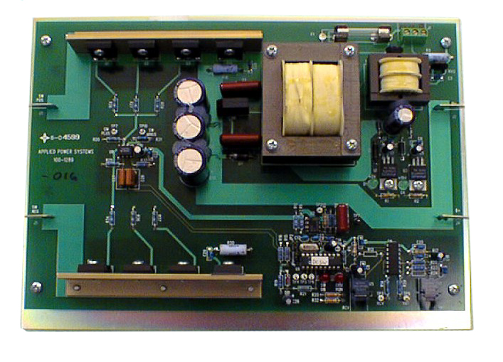
FEATURES INCLUDE APPLICATIONS The AP-1289 provides a complete, reliable, turnkey solution to control single or multiple High Voltage SCR devices. High current FET amplifiers drive individual pulse transformers that provide direct drive to each SCR gate. These encapsulated, corona resistant, high voltage pulse transformers are easily linked with supplied high voltage silicon wire to allow series stacking of multiple SCRs in order to obtain higher voltage operation. Standard Hewlett-Packard™ fiber-optic couplers provide an intrinsically safe interface and virtually infinite noise immunity between the SCR being driven and the customers’ control electronics. An on-board microcontroller provides timing and control of the SCR gating signals with crystal controlled accuracy, allowing precision phase control of the SCR being driven. An on-board power supply accepts 120VAC input and generates all power needed for the logic control, fiber-optic interface and gate drive. |
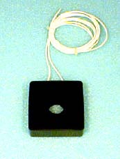
click images and diagrams to enlarge 15kV Pulse Transformer |
|
||||||||||||||||||||||||||||||||||||||||||||||||||||||||||||
|
||||||||||||||||||||||||||||||||||||||||||||||||||||||||||||
| Operation | ||||||||||||||||||||||||||||||||||||||||||||||||||||||||||||
|
After an initial 4 second Power-On delay, LED D13 (CPU Run) will flash to indicate control logic is functioning. When an optical input signal is applied to the RCV input, the AP-1289 generates a firing pulse into the primary of the pulse transformer. The pulse transformers isolated secondary drives the SCR gate input. 120 VAC Input Power should be applied to the Control board for 4 seconds minimum, prior to energizing the SCR being controlled. AC power to the board must be maintained during the entire operating period. |
||||||||||||||||||||||||||||||||||||||||||||||||||||||||||||
|
||||||||||||||||||||||||||||||||||||||||||||||||||||||||||||
|
||||||||||||||||||||||||||||||||||||||||||||||||||||||||||||


